
Technology of Autonomous Mobile Robots
Modern autonomous mobile robots from SMP Robotics combine several cutting-edge technologies into one proven solution:
- Onboard neural network video analytics — real-time processing of panoramic and PTZ camera streams without dependency on cloud latency.
- Large Language Models (LLMs) — natural interaction with humans and enhanced contextual decision-making.
- Autonomous navigation validated in the field — hundreds of thousands of kilometers of real-world operation, demonstrating reliability even in GPS-denied environments.
- Energy-efficient mobility platform — robust mechanics, automatic docking stations, high uptime, and easy serviceability.
Through this convergence, the Argus S5.3 is no longer just a concept but a standard element of security infrastructure — equally effective for industrial facilities and urban territories.
Already today, Argus S5.3 is transforming the security market by enabling Robotics-as-a-Service (RaaS) patrols at only $10/hour, creating a new benchmark for cost-efficiency and reliability.
Robots as Part of the AI Ecosystem of the Future
Autonomous mobile robots are becoming a foundation of the new AI-driven world. Operating daily in diverse environments, they generate unique datasets for training advanced machine learning models.
This continuous data collection – video, audio, thermal, and environmental – fuels the development of artificial intelligence capable of recognizing anomalies, predicting failures, and adapting behavior.
By forming a distributed ecosystem of mobile sensors and intelligent agents, robots accelerate the evolution of AI itself, making each new generation of systems more accurate, responsive, and autonomous
Future of Autonomous Mobile Robots with Artificial Intelligence
The next stage of development focuses on:
- Predictive threat detection and early anomaly recognition;
- Dynamic route adaptation based on real-time context;
- Active non-lethal deterrence as part of integrated site security.
All of this is made possible by large-scale field data accumulated from hundreds of robots already in daily operation worldwide.
SMP Robotics continues to set the pace in autonomous mobile security, combining proven hardware with rapidly evolving AI capabilities — a foundation for the next generation of safety infrastructure across industries and geographies.
Discover the Security Patrol Robot Argus S5.3
AI-Powered Autonomous Mobile Robots for Security, Inspection, and Industrial Applications.
Next-Gen AI Robots: From Security Patrols to Autonomous Planetary Rovers.
In early 2019 SMP Robotics began serial shipping of next-generation outdoor mobile robots. During the development of the automatic guidance system, a well-proven approach was used, according to which the visual navigation and GNSS were combined. This solution does not require the use of costly lidars and is therefore reasonably priced. Its control system has a low power consumption rate despite the fact that it features a multi-processor solution to process visual information.
Combining the data from multiple sources of different physical nature (video, GPS, IMU) allows the robot to navigate and move when the data from one of the sources is either inaccurate or absent. Examples are situations where the signal coming from a satellite navigation system is bad, or when there is not enough light for the visual navigation feature to work properly.
The next-generation Sхх.2 series autonomous mobile robots (models S3.2, S5.2, S6.2, and S7.2) feature the following solutions that help improve the autonomous motion stability.
The robots leverage a high-precision ground-based positioning technology that relies on the data coming from the satellite navigation system as well as corrective information from base stations.
The minimum lighting level sufficient for the visual navigation system to work during nighttime has been lowered This was achieved thanks to the new high-sensitivity video sensors.
Artificial Intelligent in new generation outdoor mobile robots
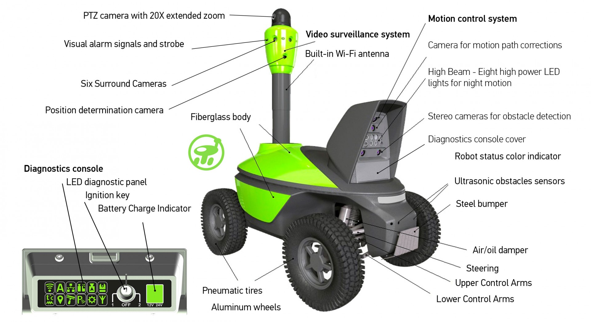
A new on-board computer was developed, with NVidia Jetson TX2 supercomputer as the basis. This solution helps to perform video surveillance and video inspection tasks more efficiently. The on-board computer makes it possible to use deep learning algorithms and AI elements during image analysis. The new obstacle avoidance system that uses a stereo image analysis technology now has an expanded vision field thanks to 2 stereo cameras and Xilinx Zink image processing.
Over the past three years, the new robot’s software has made a big leap forward. A range of new features has been added, of which the most important one is the group patrolling mode that includes integrated AI elements.
The current robot model has all the necessary hardware solutions. Their software features have just begun to be realized. It can be assumed that hardware-wise, this platform will stay up-to-date for several more years and make it possible to realize software solutions of the highest complexity.
Autonomous movement technology for small mobile robots
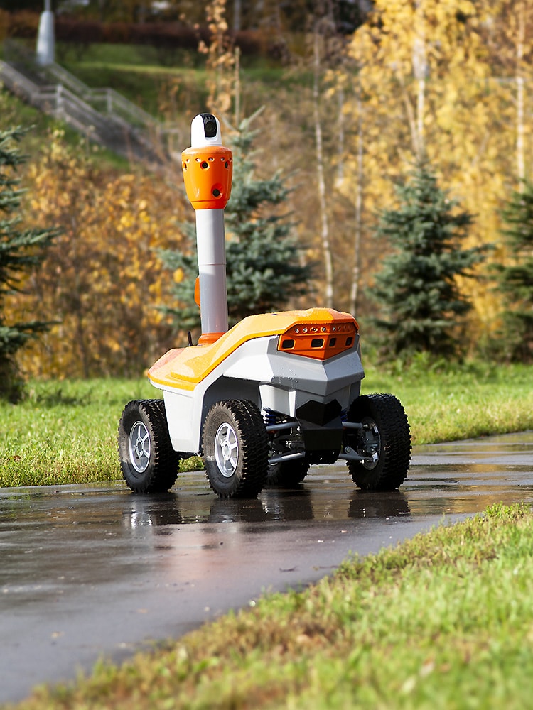
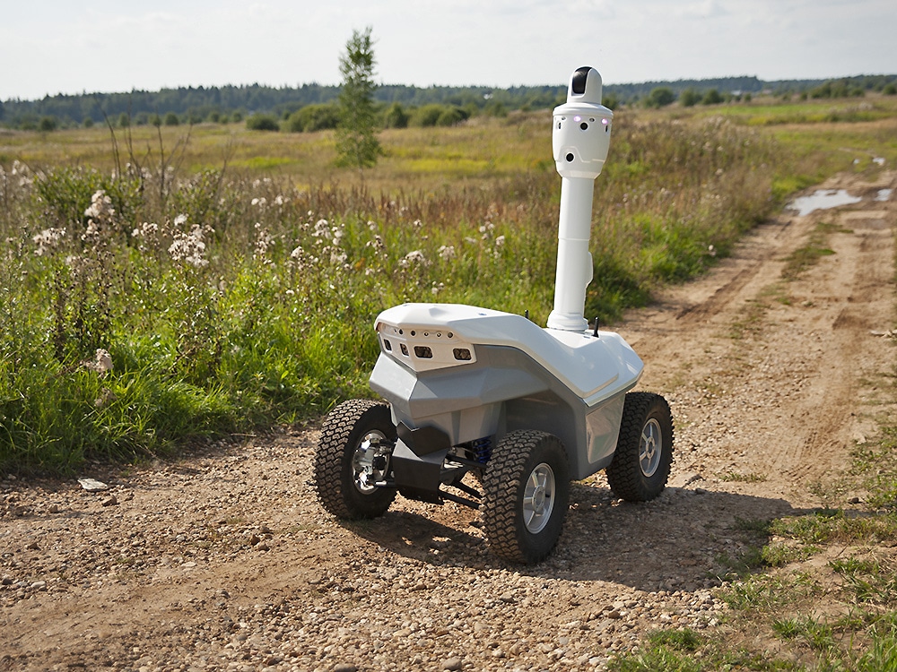
Creation of automatic motion-control technology is the most challenging stage of unmanned ground vehicle (UGV) development. Here at SMP Robotics, we have developed and scaled to practice a motion-control technology for low-speed autonomous mobile robots. At this stage of development, the technology is perfectly suited for controlling mobile robots on unmanned territories away from public roads. The autonomous motion-control system enables the robot to travel automatically along the programmed route without operator’s input. The solutions involved allow improvements in precision and increases in movement speed with each next passage.
Mobile Robot Navigation
Automatic control of the robot’s travel is based on recognition of the video feed from its on-board cameras. During the daytime, the robot follows visible ground marks within the range of its two cameras directed forward and backward. This method is effective for territories with large number of buildings and other artificial constructions. However, it is hardly suitable for open spaces with no clearly shaped objects. In this case, it is advised to plot the cruise routes along hard-surface pathways. The color difference between the pathway and other surfaces provides sufficient reference for route correction and precision navigation along the edge of the path. Combined with the satellite navigation system, this method enables highly accurate passages.
Providing light along the cruise route by the way of street lamps is necessary for automatic nighttime motion. Standard 10 lx illumination for urban walkways will suffice. If reaching the necessary illumination level on certain segments of the cruise route is impossible, night markers should be installed. These can be attached to posts, fences, or building walls.
The involved navigation technologies enable motion-control precision unattainable with GPS only and allow the robot to move in areas with poor GPS reception.
The cruise routes for robots are selected on a tablet PC powered by Android. Multi-Robot software has been developed for this purpose. The mobile PC and the robot are connected via WiFi.
The software interface screens display the digital map with the current location of the robot, system status, battery charge, and the feed from the on-board cameras. The authorized user is able to change the robot’s route, trigger the alarm and turn on the stroboscopic light, and manage the payload operating modes. The user interface software allows the user to manage several mobile robots on the same site. The robot’s motion is unaffected by wireless communication channel performance. Having entered an area with poor WiFi reception, the robot will continue to move automatically until it leaves the area, and then both data transfer and video transmission are restored.
Robot’s system status during operation is displayed by the built-in LED indicator with its colors clearly visible from several yards away. The color of the LED light indicates the battery charge, temperature inside the chassis, WiFi network status, and any system errors. The robot is switched on and off by operating personnel using a removable mechanical key. A diagnostic panel is provided for troubleshooting superficial faults.
Mobile Robot Mapping and Localization
The robot is taught the cruise route during on-site assembly. A digital passage route map is created with Google Maps. Markers are placed every 50 yards along the route. Using a remote control or a tablet, the deployment/integration engineer guides the robot along all possible passage routes in manual mode. The robot records the movement trajectory, lays it over the digital map, and aligns it to visible ground marks located along the path. The operator can correct the route in order to optimize maneuverability and assign priority checkpoints. The robot is then launched on route in automatic mode in order to gather data on visible ground marks in various lightning conditions.
The best result is achieved when training passes are performed throughout the daylight hours in a mix of cloudy and sunny conditions. Over the next few days, the robot will be traveling along the route in test mode. During this time, the markers remain on their places but are turned off. If the robot keeps covering the route in good time and with sufficient reliability, the markers are removed and the robot is ready for autonomous operation on this route. The robot may need to be reeducated for seasonal landscape changes like snowfall.
Autonomous Mobile Robot Obstacle Avoidance
Obstacles that occur on the robot’s path are detected by the built-in system of stereocameras. The stereo image processing algorithm calculates the distance to the obstacle and selects the ideal bypass route. In case obstacle bypass caused the robot to significantly deviate from the set route, the robot will stop automatically. The robot’s stereocameras define the cruise route when the robot moves along a border or a solid fence.
The robot is equipped with a low beam headlamp to provide for reliable operation of the obstacle detection system. The headlamp turns on automatically at twilight or when local illumination of the path immediately in front of the robot is insufficient.
Characteristics of the autonomous robot navigation system
| Motion-control system power consumption | 35W |
| Minimum illumination for visual navigation | 10 lx |
| Accuracy of check-point drive-through | |
| – in visual navigation mode | circle radius 2.6 ft |
| – when using night markers | circle radius 1.3 ft |
| – when using GPS only | circle radius 7.2 ft |
| Speed of automatic movement | 2.5–3.7 mph |
Autonomous guidance
systems of the
mobile robot
- Precision navigation along the programmed route
- A new route can be taught within 24 hours
- Low-power consumption of built-in computers and the whole control system
- Low cost due to lack of expensive LIDAR systems and built-in computers with high-power consumption
- Neither special road infrastructure nor road markings are required
- Stereocameras for obstacle detection and avoidance
- Video analysis of the terrain for precision navigation along pedestrian pathways
- Positioning by visible ground marks – visual navigation
- Satellite navigation system for operation in open spaces
- Night markers for operation in dimly-lit conditions


